|
|||||||||||||||||||||||||||||||||||||||||||||||||||||||||||||||||||||||||||
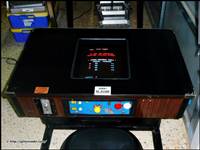
The purpose of this site is to document as much information on the little known Space Invaders rip off, IPM Invader. For those who are not aware of
IPM Invader, it is the game that has a 'coffee break' after every 3
waves of invaders. This has always fascinated me and I enjoyed reaching
the 'coffee break' when I was young. |
|||||||||||||||||||||||||||||||||||||||||||||||||||||||||||||||||||||||||||
|
|||||||||||||||||||||||||||||||||||||||||||||||||||||||||||||||||||||||||||

|
In this section I will be documenting all the technical data available to me on IPM Invader. Pin outs, schematics, manuals, pcb revision numbers, pcb sound boards, pcb cpu/rom boards and pcb pictures. IPM Invader is also a Dual sync game meaning it has separate Horizontal and Vertical outputs, and many have been modified to composite negative Horizontal sync because they won't work on most monitors. Thanks Jomac. I have managed
to track down some pinouts thanks to a friend of mine. Thanks Geoff.
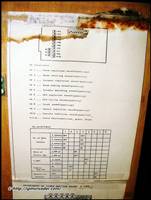
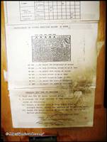
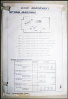
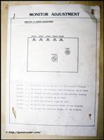
*Updated - 12 December 2013. Manual and Schematics finally found. Thanks DisQo and yohansen.
To download
the pinouts click here.
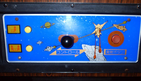
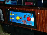
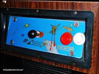
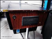
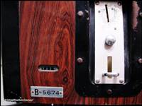
Credit: Andrew Welburn. Thanks go to Carmel Morris for supplying me with photos of an original IPM Invader cocktail control panel.
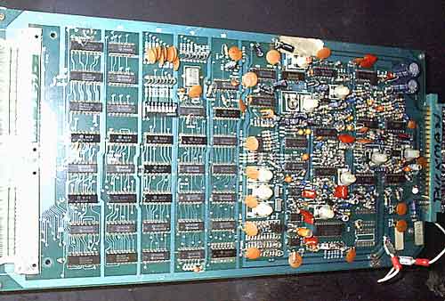
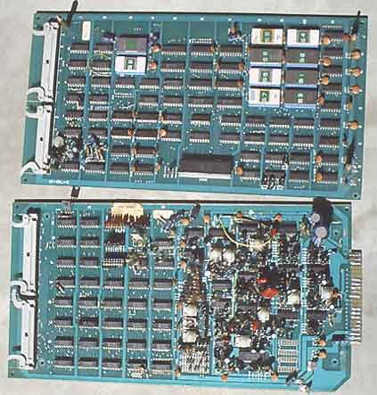
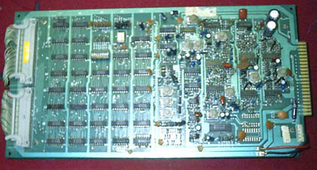
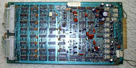
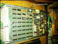
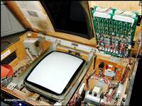
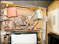
Here are some pictures of a working IPM Invader board set.
This pcb is now happily running IPM Invader.
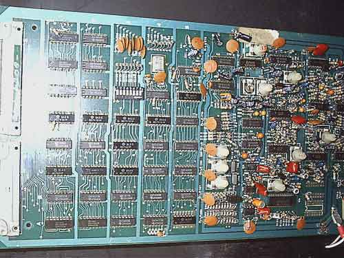
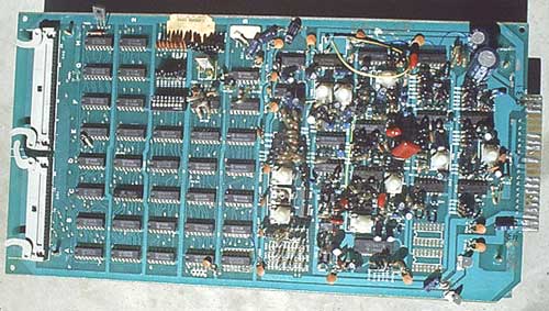
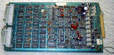
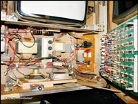
Another board set that is not working is pictured below.
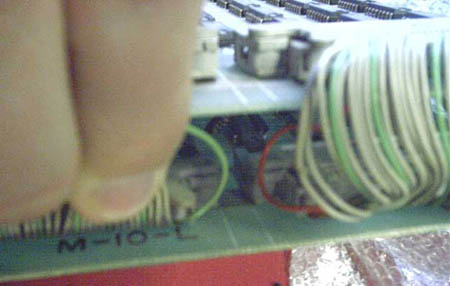
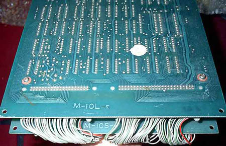
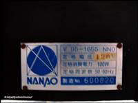
Numbers on this board set are:
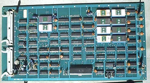
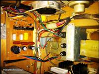
Here are another 2 different board sets from another friend.
Numbers on the 1st board set are:
Number on the 2nd board set are:
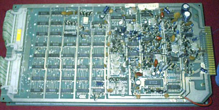
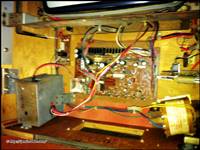
Finally I have a board set which is not working and it's a weird revision too.
Numbers on my board set are:
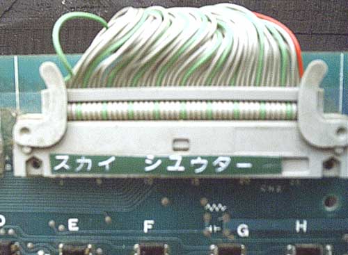
As you can see, there clearly were several hardware revisions when Irem was manufacturing these pcb's.
Will have manuals and schematics up shortly. I hope.
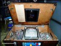
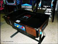
IPM Invader ROMS have been dumped for the mame project but due to the Irem skychut.c driver not being the best it could be, the game play is average at best in mame. I hope the skychut.c driver is improved in the future. Some more images of IPM Invader (click for larger image)
|
||||||||||||||||||||||||||||||||||||||||||||||||||||||||||||||||||||||||||||||||||||||||||||||||||||||||||||||||||||||||||||||||||||||||||||||||||||||||||||||||||||||||||||||||||||||||||||||||
|
All
trademarks and copyrighted materials are property of their respective
owners. 2003-2018.© |
||||||||||||||||||||||||||||||||||||||||||||||||||||||||||||||||||||||||||||||||||||||||||||||||||||||||||||||||||||||||||||||||||||||||||||||||||||||||||||||||||||||||||||||||||||||||||||||||